🎯 نواتج التعلم
🎯 Learning Outcomes
بعد دراسة هذا الدرس ستكون قادرًا على أن:
After this lesson you will be able to:
- تلخّص العلاقة بين الجهد والتيار في المقاوم والملف والمكثف (فرق الطور والمفاعلة).Summarise the relation between voltage and current in the resistor, the inductor and the capacitor (phase difference and reactance).
- تعلّل لماذا لا تُجمع الجهود والممانعات جمعًا حسابيًا في دائرة \(RLC\) على التوالي.Explain why the voltages and the impedances are not added arithmetically in a series \(RLC\) circuit.
- ترسم المخطط الاتجاهي وتحسب \(V_m\) و\(Z\) وزاوية الطور \(\phi\).Draw the phasor diagram and calculate \(V_m\), \(Z\) and the phase angle \(\phi\).
- تحدد هل الدائرة حثية أم سعوية أم في حالة رنين، ومن يسبق: الجهد أم التيار.Decide whether the circuit is inductive, capacitive or in resonance, and which one leads: the voltage or the current.
- تطبق شرط الرنين \(X_L=X_C\) وتحسب تردده \(f_0=\dfrac{1}{2\pi\sqrt{LC}}\) وتفسر استعماله في أجهزة الاستقبال.Apply the resonance condition \(X_L=X_C\), calculate its frequency \(f_0=\dfrac{1}{2\pi\sqrt{LC}}\) and explain its use in receivers.
- تشرح عمل المحول الكهربائي وتحل مسائل \(\dfrac{V_S}{V_P}=\dfrac{N_S}{N_P}\) والتيار والمقاومة الفعالة.Explain how the transformer works and solve problems on \(\dfrac{V_S}{V_P}=\dfrac{N_S}{N_P}\), the currents and the effective resistance.
🔁 مراجعة: المقاوم والملف والمكثف كلٌّ على حدة
🔁 Review: The Resistor, the Inductor and the Capacitor Separately
في الجزء الأول درسنا كل عنصر وحده مع مصدر متردد. نلخّص هنا ما سنحتاجه: فرق الطور بين جهد العنصر والتيار المار فيه، والممانعة التي يقدمها للتيار.
In Part I we studied each element alone with an AC source. Here we summarise what we need: the phase difference between the voltage of the element and the current through it, and the opposition it offers to the current.
| مقاومة أومية (R)Ohmic resistor (R) | ملف نقي (L)Pure coil (L) | مكثف (C)Capacitor (C) | |
|---|---|---|---|
| الدائرةCircuit | 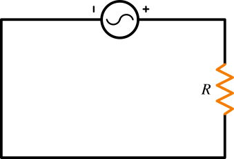 | 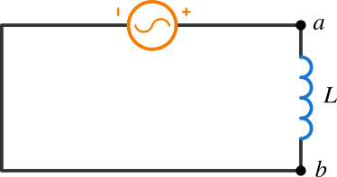 | 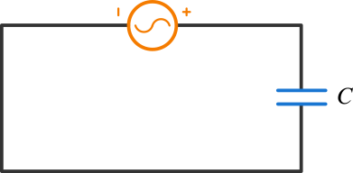 |
| الجهد (البرتقالي) والتيار (الأزرق)Voltage and current | 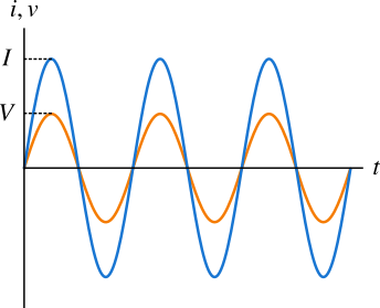 | 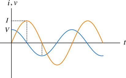 | 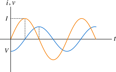 |
| المتجهاتPhasors | 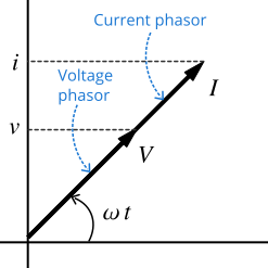 | 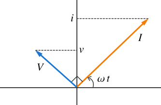 | 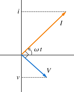 |
| فرق الطورPhase | الجهد والتيار متفقان في الطورVoltage and current are in phase | جهد الملف يسبق التيار بـ \(\dfrac{\pi}{2}\)The coil voltage leads the current by \(\dfrac{\pi}{2}\) | جهد المكثف يتأخر عن التيار بـ \(\dfrac{\pi}{2}\)The capacitor voltage lags the current by \(\dfrac{\pi}{2}\) |
| الممانعةOpposition | \(R\) | \(X_L=2\pi fL\) | \(X_C=\dfrac{1}{2\pi fC}\) |
| أعظم جهدPeak voltage | \(V_R=I_mR\) | \(V_L=I_mX_L\) | \(V_C=I_mX_C\) |
💡 شرح إضافي: كيف أتذكر من يسبق من؟
💡 Extra explanation: how do I remember who leads?
في الملف: التيار هو المتأخر (يحتاج وقتًا ليبني مجاله المغناطيسي) أي أن الجهد يسبق التيار. وفي المكثف: التيار يسبق الجهد (يجب أن يتدفق التيار أولًا ليشحن المكثف فيرتفع جهده) أي أن التيار يسبق الجهد. قاعدة تُحفظ بسهولة: «ELI the ICE man» — في الملف \(L\) الجهد \(E\) قبل التيار \(I\)، وفي المكثف \(C\) التيار \(I\) قبل الجهد \(E\).
In the inductor the current is the late one (it needs time to build its magnetic field) so the voltage leads the current. In the capacitor the current must flow first to charge it and raise its voltage, so the current leads the voltage. An easy rule is “ELI the ICE man” — in an inductor \(L\) the voltage \(E\) comes before the current \(I\), in a capacitor \(C\) the current \(I\) comes before the voltage \(E\).
🔗 دائرة ملف ومكثف ومقاوم على التوالي
🔗 The Series Coil–Capacitor–Resistor Circuit
نصل الآن العناصر الثلاثة على التوالي بمصدر متردد. بما أن التوصيل على التوالي فإن التيار هو نفسه في كل عنصر في كل لحظة، ولذلك نتخذه مرجعًا للطور:
We now connect the three elements in series to an AC source. Because they are in series the same current flows through every element at every instant, so we take it as the phase reference:
📘 معادلة التيار في الدائرة
📘 The current equation of the circuit
\[i(t)=I_m\sin(\omega t\pm\phi)\]
يكون التيار إما متقدمًا في الطور على جهد المصدر أو متأخرًا عنه، وهذا ما تحدده الزاوية \(\phi\) ونوع العنصر الغالب (ملف أم مكثف).
The current is either ahead of the source voltage in phase or behind it, and this is determined by the angle \(\phi\) and by which element dominates (coil or capacitor).
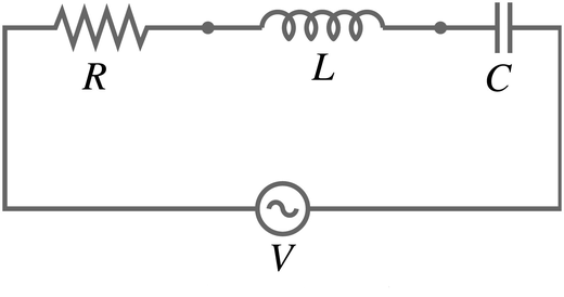
دائرة ملف ومقاوم ومكثف موصولة على التوالي بمصدر متردد.
A coil, a resistor and a capacitor connected in series to an AC source.
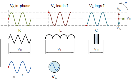
الشكل يوضح أن \(V_R\) في الطور مع التيار، و\(V_L\) تسبقه، و\(V_C\) تتأخر عنه.
A figure showing that \(V_R\) is in phase with the current, \(V_L\) leads it and \(V_C\) lags it.
السؤال: كيف نجد فرق الجهد الكلي والممانعة الكلية وزاوية الطور بين التيار والجهد؟ الجواب الأول الذي يخطر ببالنا هو الجمع الحسابي، لكنه خاطئ:
The question: how do we find the total voltage, the total impedance and the phase angle between the current and the voltage? The first answer that comes to mind is the arithmetic sum, but it is wrong:
⚠️ لا يصح الجمع الحسابي
⚠️ The arithmetic sum is not valid
\[V_m\neq V_R+V_L+V_C\]
\[Z\neq R+X_L+X_C\]
💡 شرح إضافي: لماذا لا نجمع الجهود جمعًا حسابيًا؟
💡 Extra explanation: why can we not add the voltages arithmetically?
جهود العناصر الثلاثة لا تبلغ قيمها العظمى في اللحظة نفسها: \(V_R\) تبلغ قمتها مع التيار، و\(V_L\) قبله بربع دورة، و\(V_C\) بعده بربع دورة. الجمع الحسابي للقيم العظمى يفترض أنها تتزامن، وهذا غير صحيح. لذلك نمثل كل جهد بمتجه دوّار طوله القيمة العظمى واتجاهه يحدده الطور، ونجمع المتجهات.
The voltages of the three elements do not reach their peak values at the same instant: \(V_R\) peaks with the current, \(V_L\) a quarter of a cycle before it and \(V_C\) a quarter of a cycle after it. Adding the peaks arithmetically assumes they coincide, which is false. So we represent each voltage by a rotating phasor whose length is the peak value and whose direction is set by the phase, and we add the phasors.
مثال عددي: إذا كانت \(R=30\ \Omega\) و\(X_L=40\ \Omega\) فقط فإن \(Z=\sqrt{30^2+40^2}=50\ \Omega\) وليس \(70\ \Omega\).
Numerical example: if only \(R=30\ \Omega\) and \(X_L=40\ \Omega\) are present then \(Z=\sqrt{30^2+40^2}=50\ \Omega\) and not \(70\ \Omega\).
📐 المخطط الاتجاهي: الجهد الكلي والممانعة وزاوية الطور
📐 The Phasor Diagram: Total Voltage, Impedance and Phase Angle
نرسم الجهود كمتجهات مع اعتبار التيار على المحور الأفقي، وفق الخطوات الآتية:
We draw the voltages as phasors with the current on the horizontal axis, using these steps:
🪜 خطوات الرسم
🪜 Drawing steps
- نرسم \(V_R\) على المحور الأفقي (في طور التيار).Draw \(V_R\) on the horizontal axis (in phase with the current).
- نرسم \(V_L\) عموديًا إلى الأعلى (تسبق التيار بـ \(90^\circ\)) و\(V_C\) عموديًا إلى الأسفل (تتأخر عنه بـ \(90^\circ\)).Draw \(V_L\) vertically upward (it leads the current by \(90^\circ\)) and \(V_C\) vertically downward (it lags it by \(90^\circ\)).
- المتجهان \(V_L\) و\(V_C\) متعاكسان فنطرحهما: \(V_L-V_C\) والناتج باتجاه المتجه الأكبر.\(V_L\) and \(V_C\) are opposite so we subtract them: \(V_L-V_C\) and the result points in the direction of the larger one.
- ننقل متجه الفرق إلى رأس \(V_R\).Move the difference phasor to the head of \(V_R\).
- المحصلة من الذيل إلى الرأس هي \(V_m\) (جهد المصدر الأعظم)، وتصنع مع محور التيار الزاوية \(\phi\).The resultant from the tail to the head is \(V_m\) (the peak source voltage), making the angle \(\phi\) with the current axis.
المخطط الاتجاهي للجهود: \(V_R\) على محور التيار، \(V_L\) إلى الأعلى، \(V_C\) إلى الأسفل، ومحصلتها \(V_m\).
The voltage phasor diagram: \(V_R\) along the current axis, \(V_L\) upward, \(V_C\) downward, and their resultant \(V_m\).
المثلث قائم الزاوية، ومنه بفيثاغورس:
The triangle is right-angled, so by Pythagoras:
📘 الجهد الكلي والممانعة وزاوية الطور
📘 Total voltage, impedance and phase angle
\[V_m^2=V_R^2+(V_L-V_C)^2\]
بتعويض \(V_R=I_mR\) و\(V_L=I_mX_L\) و\(V_C=I_mX_C\) وبما أن التيار \(I_m\) واحد في التوالي يمكن اختصاره من الطرفين:
Substituting \(V_R=I_mR\), \(V_L=I_mX_L\) and \(V_C=I_mX_C\), and since the current \(I_m\) is the same in series, it cancels from both sides:
\[I_m^2Z^2=I_m^2R^2+I_m^2(X_L-X_C)^2\ \Rightarrow\ Z^2=R^2+(X_L-X_C)^2\]
\[I_m=\dfrac{V_m}{Z}\qquad \phi=\tan^{-1}\dfrac{V_L-V_C}{V_R}=\tan^{-1}\dfrac{X_L-X_C}{R}\]
زاوية الطور \(\phi\) هي الزاوية بين التيار وفرق جهد المصدر:
The phase angle \(\phi\) is the angle between the current and the source voltage:
| الحالةCase | إشارة \(\phi\)Sign of \(\phi\) | من يسبق؟Who leads? | طبيعة الدائرةNature of the circuit |
|---|---|---|---|
| \(X_L\gt X_C\)\(X_L\gt X_C\) | موجبةpositive | الجهد يسبق التيارthe voltage leads the current | حثيةinductive |
| \(X_L\lt X_C\)\(X_L\lt X_C\) | سالبةnegative | التيار يسبق الجهدthe current leads the voltage | سعويةcapacitive |
| \(X_L=X_C\)\(X_L=X_C\) | صفرzero | متفقان في الطورin phase | رنينresonance |
💡 شرح إضافي: تأثير التردد في طبيعة الدائرة
💡 Extra explanation: the effect of the frequency on the nature of the circuit
\(X_L=2\pi fL\) تزداد مع التردد، و\(X_C=\dfrac{1}{2\pi fC}\) تنقص معه. لذلك عند التردد المنخفض تكون \(X_C\) الأكبر فتسلك الدائرة سلوكًا سعويًا، وعند التردد المرتفع تكون \(X_L\) الأكبر فتسلك سلوكًا حثيًا، وعند تردد واحد معيّن تتساويان وهو تردد الرنين.
\(X_L=2\pi fL\) grows with the frequency and \(X_C=\dfrac{1}{2\pi fC}\) shrinks with it. So at a low frequency \(X_C\) is the larger and the circuit behaves capacitively, at a high frequency \(X_L\) is the larger and it behaves inductively, and at one particular frequency they are equal: the resonance frequency.
وللحصول على \(\phi\) مباشرة من الأرقام نكتبها بحسب الإشارة: \(\phi\gt 0\) تعني أن الجهد يتقدم، فتكتب المعادلتان \(v=V_m\sin(\omega t+\phi)\) و\(i=I_m\sin\omega t\). وإن اتخذنا الجهد مرجعًا \(v=V_m\sin\omega t\) كان \(i=I_m\sin(\omega t-\phi)\).
To get \(\phi\) straight from the numbers we keep its sign: \(\phi\gt 0\) means the voltage is ahead, so the two equations are \(v=V_m\sin(\omega t+\phi)\) and \(i=I_m\sin\omega t\). If we take the voltage as the reference \(v=V_m\sin\omega t\) then \(i=I_m\sin(\omega t-\phi)\).
🧪 تجربة 1: دائرة RLC على التوالي: الممانعة وزاوية الطور
🧪 Experiment 1: Series RLC circuit: impedance and phase angle
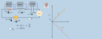
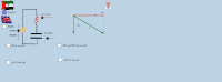
ملف ومكثف ومقاوم موصولة على التوالي بمصدر متردد. التيار واحد في كل العناصر (مرجع الطور)، أما الجهود فتختلف في الطور: \(V_R\) مع التيار، \(V_L\) تسبقه \(90^\circ\)، \(V_C\) تتأخر عنه \(90^\circ\). المخطط الاتجاهي يرسم المثلث \(V_m^2=V_R^2+(V_L-V_C)^2\) ومنه \(Z\) و\(\phi\). غيّر المتغيرات أو اختر حالة جاهزة (غلبة حثية، غلبة سعوية، رنين)، ثم احسب القيم المطلوبة في الجدول واضغط «تحقق». (العرض مبطّأ.)
A coil, a capacitor and a resistor are connected in series to an AC source. The same current flows in every element (the phase reference) but the voltages differ in phase: \(V_R\) is with the current, \(V_L\) leads it by \(90^\circ\), \(V_C\) lags it by \(90^\circ\). The phasor diagram draws the triangle \(V_m^2=V_R^2+(V_L-V_C)^2\) from which \(Z\) and \(\phi\) follow. Change the variables or choose a ready case (inductive, capacitive, resonance), then calculate the required values in the table and press “Check”. (The display is slowed.)
✏️ الجدول المطلوب (للطالب): احسب القيم للمتغيرات الحالية في المحاكاة ثم اضغط «تحقق» (يُقبل خطأ نسبي صغير).
✏️ The required table (for the student): calculate the values for the present variables of the simulation then press “Check” (a small relative error is accepted).
دائرة \(RLC\) على التوالي مفاعلة ملفها أكبر من مفاعلة مكثفها \(X_L\gt X_C\). أي العبارات صحيحة؟
A series \(RLC\) circuit has a coil reactance greater than the capacitor reactance \(X_L\gt X_C\). Which statement is correct?
في دائرة \(RLC\) على التوالي كانت \(V_R=60\ \mathrm{V}\) و\(V_L=140\ \mathrm{V}\) و\(V_C=60\ \mathrm{V}\). جهد المصدر الأعظم:
In a series \(RLC\) circuit \(V_R=60\ \mathrm{V}\), \(V_L=140\ \mathrm{V}\) and \(V_C=60\ \mathrm{V}\). The peak source voltage is:
✍️ أمثلة محلولة على الدائرة
✍️ Worked Examples on the Circuit
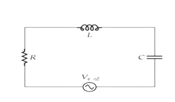
دائرة \(RLC\) على التوالي بمصدر متردد (للمثال 1).
A series \(RLC\) circuit with an AC source (for Example 1).
دائرة \(RLC\) على التوالي موصولة بمصدر معادلته \(V(t)=210\sin(300t)\)، وكان \(L=0.5\ \mathrm{H}\) و\(C=5\ \mu\mathrm{F}\) و\(R=150\ \Omega\). احسب الممانعة \(Z\) وأعظم تيار وزاوية الطور، واكتب معادلة التيار.
A series \(RLC\) circuit is connected to a source with equation \(V(t)=210\sin(300t)\), with \(L=0.5\ \mathrm{H}\), \(C=5\ \mu\mathrm{F}\) and \(R=150\ \Omega\). Calculate the impedance \(Z\), the peak current and the phase angle, and write the current equation.
في دائرة \(RLC\) على التوالي مررنا تيارًا أعظمه \(2\ \mathrm{A}\) بتردد \(50\ \mathrm{Hz}\)، وكانت \(R=30\ \Omega\) و\(L=100\ \mathrm{mH}\) و\(C=50\ \mu\mathrm{F}\). احسب \(X_L\) و\(X_C\) وجهد كل عنصر والجهد الكلي والممانعة وزاوية الطور (كما في جدول التجربة العملية).
A peak current of \(2\ \mathrm{A}\) at \(50\ \mathrm{Hz}\) flows in a series \(RLC\) circuit with \(R=30\ \Omega\), \(L=100\ \mathrm{mH}\) and \(C=50\ \mu\mathrm{F}\). Calculate \(X_L\), \(X_C\), the voltage of each element, the total voltage, the impedance and the phase angle (as in the practical-experiment table).
دائرة \(RLC\) على التوالي: \(R=30\ \Omega\) و\(X_L=70\ \Omega\) و\(X_C=30\ \Omega\) وجهد المصدر الأعظم \(100\ \mathrm{V}\). احسب \(Z\) و\(I_m\) و\(\phi\) و\(V_R\) و\(V_L\) و\(V_C\).
A series \(RLC\) circuit: \(R=30\ \Omega\), \(X_L=70\ \Omega\), \(X_C=30\ \Omega\) and the peak source voltage is \(100\ \mathrm{V}\). Calculate \(Z\), \(I_m\), \(\phi\), \(V_R\), \(V_L\) and \(V_C\).
في دائرة \(RLC\) على التوالي قيمة \(X_L=40\ \Omega\) و\(X_C=40\ \Omega\) و\(R=25\ \Omega\). الممانعة الكلية:
In a series \(RLC\) circuit \(X_L=40\ \Omega\), \(X_C=40\ \Omega\) and \(R=25\ \Omega\). The total impedance is:
📻 الرنين في دائرة \(RLC\)
📻 Resonance in the \(RLC\) Circuit
تستعمل دوائر الرنين في أجهزة استقبال الراديو والتلفاز. نغيّر تردد المصدر (أو سعة المكثف أو معامل الحث الذاتي للملف) إلى أن نصل إلى الرنين. وعادةً نغيّر التردد حتى تنخفض ممانعة الدائرة فتسمح بمرور التيار القادم من الهوائي الذي يساوي تردده تردد الدائرة، بينما تُضعف الترددات الأخرى.
Resonance circuits are used in radio and television receivers. We change the source frequency (or the capacitance of the capacitor or the self-inductance of the coil) until resonance occurs. We usually change the frequency until the impedance of the circuit drops and lets pass the current coming from the antenna whose frequency equals that of the circuit, while the other frequencies are weakened.
📘 شرط الرنين ونتائجه
📘 The resonance condition and its results
\[X_L=X_C\ \Rightarrow\ Z=R\ (\text{minimum})\]
\[I_m=\dfrac{V_m}{R}\ (\text{maximum})\qquad V_L=V_C\qquad V_m=V_R\qquad \phi=0\]
\[f_0=\dfrac{1}{2\pi\sqrt{LC}}\]
عند الرنين تصبح الدائرة وكأن فيها مقاومة فقط: التيار والجهد متفقان في الطور.
At resonance the circuit behaves as if it contained only a resistance: the current and the voltage are in phase.
💡 شرح إضافي: من أين جاء قانون تردد الرنين؟
💡 Extra explanation: where does the resonance-frequency law come from?
نساوي المفاعلتين: \(2\pi fL=\dfrac{1}{2\pi fC}\) فيكون \((2\pi f)^2=\dfrac{1}{LC}\) ومنه \(f_0=\dfrac{1}{2\pi\sqrt{LC}}\). لاحظ أنه لا يتوقف على \(R\): المقاومة لا تغيّر تردد الرنين، لكنها تحدد ارتفاع القمة \(I_m=V_m/R\) وعرضها (زيادة \(R\) تخفض القمة وتعرّضها).
We equate the reactances: \(2\pi fL=\dfrac{1}{2\pi fC}\) so \((2\pi f)^2=\dfrac{1}{LC}\) and \(f_0=\dfrac{1}{2\pi\sqrt{LC}}\). Notice that it does not depend on \(R\): the resistance does not change the resonance frequency but it sets the height of the peak \(I_m=V_m/R\) and its width (increasing \(R\) lowers and widens the peak).
ملاحظة مهمة: عند الرنين قد يكون \(V_L=V_C\) أكبر بكثير من جهد المصدر، لأن \(V_L=I_mX_L=\dfrac{V_m}{R}X_L\). ويسمى النسبة \(Q=\dfrac{X_L}{R}\) عامل الجودة؛ كلما كان \(R\) صغيرًا كانت القمة أعلى وأدق (انتقائية أعلى للمحطة المطلوبة).
Important note: at resonance \(V_L=V_C\) may be much larger than the source voltage, because \(V_L=I_mX_L=\dfrac{V_m}{R}X_L\). The ratio \(Q=\dfrac{X_L}{R}\) is called the quality factor; the smaller \(R\) is, the higher and sharper the peak (higher selectivity for the wanted station).
🧪 تجربة 2: الرنين: منحنى التيار بدلالة التردد
🧪 Experiment 2: Resonance: the current versus frequency
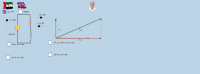
غيّر تردد المصدر وراقب منحنى \(I_m(f)=\dfrac{V_m}{\sqrt{R^2+(X_L-X_C)^2}}\) (\(V_m=100\ \mathrm{V}\)). عند \(X_L=X_C\) تبلغ الممانعة أصغر قيمة \(Z=R\) ويصل التيار إلى أعظم قيمة \(V_m/R\) وتكون \(V_L=V_C\) و\(V_R=V_m\). تردد الرنين \(f_0=\dfrac{1}{2\pi\sqrt{LC}}\) لا يتأثر بـ \(R\)؛ لكن زيادة \(R\) تُخفض القمة وتعرّضها. اضغط «اذهب إلى الرنين» ثم جرّب تغيير \(L\) و\(C\) و\(R\).
Change the source frequency and watch the curve \(I_m(f)=\dfrac{V_m}{\sqrt{R^2+(X_L-X_C)^2}}\) (\(V_m=100\ \mathrm{V}\)). At \(X_L=X_C\) the impedance is smallest \(Z=R\), the current reaches its maximum \(V_m/R\), \(V_L=V_C\) and \(V_R=V_m\). The resonance frequency \(f_0=\dfrac{1}{2\pi\sqrt{LC}}\) is not affected by \(R\); but increasing \(R\) lowers the peak and widens it. Press “Go to resonance” then try changing \(L\), \(C\) and \(R\).
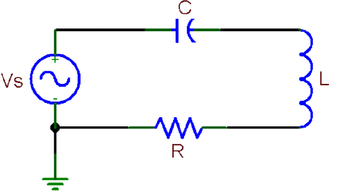
دائرة \(RLC\) على التوالي (للمثالين 4 و5).
A series \(RLC\) circuit (for Examples 4 and 5).
دائرة \(RLC\) على التوالي جهد مصدرها الأعظم \(V_m=240\ \mathrm{V}\)، وكان جهد المقاوم الأعظم \(V_R=120\ \mathrm{V}\) في البداية. غُيّر تردد المصدر حتى أصبح \(V_L=V_C\). أوجد أعظم قيمة يصل إليها التيار علمًا بأن \(R=160\ \Omega\).
A series \(RLC\) circuit has a peak source voltage \(V_m=240\ \mathrm{V}\) and a resistor voltage \(V_R=120\ \mathrm{V}\) at the start. The source frequency was changed until \(V_L=V_C\). Find the maximum current the circuit can reach given \(R=160\ \Omega\).
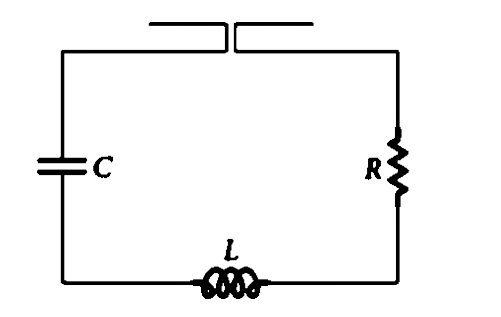
دائرة رنين متصلة بهوائي (للمثال 5).
A resonance circuit connected to an antenna (for Example 5).
دائرة رنين \(RLC\) متصلة بهوائي، تحتوي على ملف معامل حثه الذاتي \(L=0.03\ \mathrm{H}\) ومكثف سعته \(C=2\ \mu\mathrm{F}\). ما تردد الموجة التي تستطيع استقبالها؟
An \(RLC\) resonance circuit connected to an antenna contains a coil of self-inductance \(L=0.03\ \mathrm{H}\) and a capacitor of capacitance \(C=2\ \mu\mathrm{F}\). What is the frequency of the wave it can receive?
ملف \(L=25\ \mathrm{mH}\) ومقاومة \(R=10\ \Omega\) في دائرة مصدرها \(V_m=50\ \mathrm{V}\). ما السعة اللازمة لرنين عند \(1\ \mathrm{kHz}\)؟ وما التيار وجهد الملف عندئذ؟
A coil \(L=25\ \mathrm{mH}\) and a resistance \(R=10\ \Omega\) are in a circuit with a source \(V_m=50\ \mathrm{V}\). What capacitance is needed for resonance at \(1\ \mathrm{kHz}\)? What are the current and the coil voltage then?
عند الرنين في دائرة \(RLC\) على التوالي يكون التيار:
At resonance in a series \(RLC\) circuit the current is:
إذا زدنا سعة المكثف في دائرة الرنين فإن تردد الرنين:
If we increase the capacitance in a resonance circuit the resonance frequency:
عند زيادة المقاومة \(R\) في دائرة رنين فإن:
When the resistance \(R\) of a resonance circuit is increased:
🔌 المحولات الكهربائية
🔌 Electrical Transformers
يُستخدم المحول لرفع الجهد الكهربائي أو خفضه. ويتكون من:
The transformer is used to step the electrical voltage up or down. It consists of:
🧩 مكونات المحول
🧩 Parts of the transformer
- ملف ابتدائي (\(N_P\) لفة) متصل بمصدر تيار متردد.A primary coil (\(N_P\) turns) connected to an AC source.
- ملف ثانوي (\(N_S\) لفة) متصل بجهاز (حمل).A secondary coil (\(N_S\) turns) connected to a device (load).
- نواة من الحديد تنقل التدفق المغناطيسي من الابتدائي إلى الثانوي.An iron core that carries the magnetic flux from the primary to the secondary.
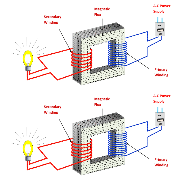
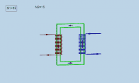
محول: ملف ابتدائي وملف ثانوي ونواة حديدية، والتدفق المغناطيسي يمر في النواة.
A transformer: a primary winding, a secondary winding and an iron core; the magnetic flux passes through the core.
يعتمد عمله على ظاهرة الحث المتبادل: يتغير التيار في الملف الابتدائي فيتغير التدفق المغناطيسي عبر الملف الثانوي، فيتولد فيه فرق جهد مستحث وتيار مستحث. وبسبب نواة الحديد يمر التدفق نفسه (وتغيّره نفسه) في الملفين، فيكون فرق الجهد المستحث في كل ملف (قانون فاراداي):
It works by mutual induction: the current in the primary coil changes so the magnetic flux through the secondary coil changes, inducing a voltage and a current in it. Because of the iron core the same flux (and the same rate of change) passes through both coils, so the induced voltage in each coil (Faraday’s law) is:
📘 نسبة الجهود إلى نسبة اللفات
📘 The voltage ratio and the turns ratio
\[V_S=-N_S\dfrac{d\Phi_B}{dt}\qquad V_P=-N_P\dfrac{d\Phi_B}{dt}\]
وبقسمة المعادلتين:
Dividing the two equations:
\[\dfrac{N_S}{N_P}=\dfrac{V_S}{V_P}\]
| الحالةCase | نوع المحولType of transformer | الجهد الثانويSecondary voltage |
|---|---|---|
| \(N_P\gt N_S\)\(N_P\gt N_S\) | خافض للجهدstep-down | أصغر من الابتدائيsmaller than the primary |
| \(N_P\lt N_S\)\(N_P\lt N_S\) | رافع للجهدstep-up | أكبر من الابتدائيlarger than the primary |
| \(N_P=N_S\)\(N_P=N_S\) | محول عزلisolation transformer | يساوي الابتدائيequal to the primary |
💡 شرح إضافي: القدرة والتيار في المحول
💡 Extra explanation: power and current in the transformer
عند وصل جهاز (مقاومة) بالملف الثانوي يمر فيه تيار \(I_S\) وتصبح هناك قدرة في الثانوي \(P_S=I_SV_S\). وهذا التيار يولّد مجالًا مغناطيسيًا في الثانوي يعاكس (قانون لنز) تغيّر التدفق، فيظهر في الابتدائي تيار أكبر ليحافظ على جهده الأصلي. أي أن ما يسحبه الابتدائي يزداد بازدياد ما يأخذه الحمل، وفي المحول المثالي (بلا فقد في الطاقة) تتساوى القدرتان.
When a device (a resistance) is connected to the secondary coil a current \(I_S\) flows in it and there is power in the secondary \(P_S=I_SV_S\). This current creates a magnetic field in the secondary that opposes (Lenz’s law) the change of the flux, so a larger current appears in the primary to keep its original voltage. So what the primary draws grows with what the load takes, and in the ideal transformer (with no energy loss) the two powers are equal.
\[P_S=P_P\ \Rightarrow\ I_SV_S=I_PV_P\ \Rightarrow\ \dfrac{I_S}{I_P}=\dfrac{V_P}{V_S}=\dfrac{N_P}{N_S}\]
من هذه العلاقة العكسية بين الجهد والتيار: المحول الرافع للجهد خافض للتيار، والمحول الخافض للجهد رافع للتيار (ولا يمكن أن يرفع محول القدرة).
From this inverse relation between voltage and current: a step-up transformer is a step-down for the current, and a step-down transformer is a step-up for the current (a transformer cannot raise the power).
في المحولات الحقيقية تضيع جزء من الطاقة حرارةً في أسلاك الملفين (\(I^2R\)) وفي النواة بسبب التيارات الدوامية والتخلّف المغناطيسي، لذلك تُصنع النواة من شرائح حديد معزولة، وتكون كفاءة المحولات الكبيرة قريبة جدًا من \(100\%\).
In real transformers part of the energy is lost as heat in the wires of the two coils (\(I^2R\)) and in the core because of eddy currents and magnetic hysteresis, so the core is made of insulated iron laminations, and large transformers have efficiencies very close to \(100\%\).
🛡️ معلومة مفيدة: محول العزل
🛡️ Useful information: the isolation transformer
محولات العزل لا ترفع الجهد ولا تخفضه، وعدد لفات ملفيها الابتدائي والثانوي متساوٍ. تُستخدم لعزل دائرة عن أخرى في الأجهزة المهمة حتى لا تتداخل التيارات (ولحماية المستخدم من التماس المباشر بالشبكة).
Isolation transformers neither step the voltage up nor down; the numbers of turns of their primary and secondary coils are equal. They are used to isolate one circuit from another in important devices so that the currents do not interfere (and to protect the user from direct contact with the mains).
وعندما يكون الحمل مقاومة \(R\) في الثانوي، يمكن حساب تيار الابتدائي والمقاومة الفعالة التي يراها المصدر:
When the load is a resistance \(R\) in the secondary, we can calculate the primary current and the effective resistance that the source sees:
📘 تيار الابتدائي والمقاومة الفعالة
📘 The primary current and the effective resistance
\[I_P=\left(\dfrac{N_S}{N_P}\right)^2\dfrac{V_P}{R}\qquad R_P=\left(\dfrac{N_P}{N_S}\right)^2R\]
الاشتقاق: \(V_S=V_P\dfrac{N_S}{N_P}\) و\(I_S=\dfrac{V_S}{R}\) و\(I_P=I_S\dfrac{N_S}{N_P}\) فيكون \(I_P=\dfrac{V_PN_S^2}{RN_P^2}\). والمقاومة الفعالة \(R_P=\dfrac{V_P}{I_P}\).
Derivation: \(V_S=V_P\dfrac{N_S}{N_P}\), \(I_S=\dfrac{V_S}{R}\) and \(I_P=I_S\dfrac{N_S}{N_P}\) so \(I_P=\dfrac{V_PN_S^2}{RN_P^2}\). The effective resistance is \(R_P=\dfrac{V_P}{I_P}\).
🧪 تجربة 3: المحول الكهربائي
🧪 Experiment 3: The transformer
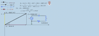
تيار متردد في الملف الابتدائي \(N_P\) يُغيّر التدفق في النواة الحديدية فيُستحث في الثانوي \(N_S\) جهد: \(\dfrac{V_S}{V_P}=\dfrac{N_S}{N_P}\). في المحول المثالي \(P_S=P_P\) أي \(\dfrac{I_S}{I_P}=\dfrac{N_P}{N_S}\). غيّر عدد اللفات والجهد والحمل \(R\) وراقب الجهدين (الأحمر ابتدائي والأزرق ثانوي) والتيارين والقدرة والمقاومة الفعالة المرئية من المصدر \(R_P=(N_P/N_S)^2R\).
An alternating current in the primary coil \(N_P\) changes the flux in the iron core so a voltage is induced in the secondary \(N_S\): \(\dfrac{V_S}{V_P}=\dfrac{N_S}{N_P}\). In the ideal transformer \(P_S=P_P\) so \(\dfrac{I_S}{I_P}=\dfrac{N_P}{N_S}\). Change the numbers of turns, the voltage and the load \(R\) and watch the two voltages (red primary, blue secondary), the two currents, the power and the effective resistance seen by the source \(R_P=(N_P/N_S)^2R\).
محول مثالي عدد لفات ملفه الابتدائي \(500\) والثانوي \(100\) وُصل ابتدائيه بمصدر جهده الأعظم \(220\ \mathrm{V}\) وثانويه بمقاومة \(R=22\ \Omega\). احسب \(V_S\) و\(I_S\) و\(I_P\) و\(R_P\).
An ideal transformer has \(500\) turns in its primary and \(100\) in its secondary. Its primary is connected to a source of peak voltage \(220\ \mathrm{V}\) and its secondary to a resistance \(R=22\ \Omega\). Calculate \(V_S\), \(I_S\), \(I_P\) and \(R_P\).
محول عدد لفات ابتدائيه \(100\) وثانويه \(400\) وجهد ابتدائه الأعظم \(50\ \mathrm{V}\) وحمله \(R=80\ \Omega\). احسب \(I_P\) بالعلاقة المباشرة ثم تحقق.
A transformer has \(100\) primary turns and \(400\) secondary turns, a primary peak voltage of \(50\ \mathrm{V}\) and a load \(R=80\ \Omega\). Calculate \(I_P\) with the direct relation and then check it.
محول ابتدائيه \(1000\) لفة وثانويه \(50\) لفة موصول بجهد \(220\ \mathrm{V}\). الجهد الثانوي:
A transformer has a \(1000\)-turn primary and a \(50\)-turn secondary connected to \(220\ \mathrm{V}\). The secondary voltage is:
في محول مثالي رافع للجهد فإن تيار الثانوي مقارنة بتيار الابتدائي:
In an ideal step-up transformer the secondary current compared with the primary current is:
يعمل المحول بالتيار المتردد وليس بالتيار المستمر الثابت لأن:
The transformer works with alternating current and not with a steady direct current because:
📚 ملخص الدرس
📚 Lesson Summary
| المفهومConcept | القانونLaw |
|---|---|
| الممانعة الكليةTotal impedance | \(Z=\sqrt{R^2+(X_L-X_C)^2}\)\(Z=\sqrt{R^2+(X_L-X_C)^2}\) |
| الجهد الكليTotal voltage | \(V_m=\sqrt{V_R^2+(V_L-V_C)^2}\ ,\ I_m=V_m/Z\)\(V_m=\sqrt{V_R^2+(V_L-V_C)^2}\ ,\ I_m=V_m/Z\) |
| زاوية الطورPhase angle | \(\phi=\tan^{-1}\dfrac{X_L-X_C}{R}\)\(\phi=\tan^{-1}\dfrac{X_L-X_C}{R}\) |
| الرنينResonance | \(X_L=X_C\ ,\ Z=R\ ,\ f_0=\dfrac{1}{2\pi\sqrt{LC}}\)\(X_L=X_C\ ,\ Z=R\ ,\ f_0=\dfrac{1}{2\pi\sqrt{LC}}\) |
| المحول المثاليIdeal transformer | \(\dfrac{V_S}{V_P}=\dfrac{N_S}{N_P}=\dfrac{I_P}{I_S}\)\(\dfrac{V_S}{V_P}=\dfrac{N_S}{N_P}=\dfrac{I_P}{I_S}\) |
| المقاومة الفعالةEffective resistance | \(R_P=(N_P/N_S)^2R\)\(R_P=(N_P/N_S)^2R\) |
⚠️ أخطاء شائعة
⚠️ Common mistakes
- جمع \(R+X_L+X_C\) أو \(V_R+V_L+V_C\) جمعًا حسابيًا؛ الصحيح الجمع الاتجاهي (فيثاغورس).Adding \(R+X_L+X_C\) or \(V_R+V_L+V_C\) arithmetically; the correct way is the phasor sum (Pythagoras).
- نسيان أن \(X_L\) و\(X_C\) يُطرحان لا يُجمعان لأنهما متعاكسان: \(X_L-X_C\).Forgetting that \(X_L\) and \(X_C\) are subtracted, not added, because they are opposite: \(X_L-X_C\).
- الخلط بين إشارة \(\phi\) ومن يسبق: \(\phi\gt 0\) تعني الجهد يسبق التيار (حثية).Confusing the sign of \(\phi\) with who leads: \(\phi\gt 0\) means the voltage leads the current (inductive).
- الاعتقاد بأن \(V_L\) أو \(V_C\) لا تتجاوز جهد المصدر؛ قد تتجاوزه كثيرًا (خاصة عند الرنين).Believing that \(V_L\) or \(V_C\) cannot exceed the source voltage; they can exceed it greatly (especially at resonance).
- الاعتقاد بأن المحول يرفع القدرة؛ يرفع الجهد على حساب التيار والقدرة ثابتة (في المثالي).Believing that a transformer raises the power; it raises the voltage at the expense of the current and the power stays constant (in the ideal one).
🧪 اختبر نفسك: امتحان من 20 سؤالاً
🧪 Test Yourself: a 20-Question Exam
أنهِ الدرس بالاختبار التفاعلي التالي؛ أسئلته تجمع بين الفهم والحساب وتغطي جميع أقسام الدرس.
Finish with the interactive exam below; its questions mix understanding with calculation and cover every section of the lesson.
اختبار التيار المتردد الجزء الثاني (12A) Alternating Current Part II (12A) Quiz
20 سؤالاً - دائرة RLC على التوالي والرنين والمحول الكهربائي 20 Questions - the series RLC circuit, resonance and the transformer
• عدد الأسئلة: 20 سؤالاً
• مدة الاختبار: 30 دقيقة
• لا يمكنك تغيير إجاباتك أو إعادة الاختبار إلا بعد 24 ساعة من التسليم.
• تأكد من إجاباتك قبل التسليم! 📌 Important Instructions:
• Number of questions: 20 questions
• Quiz duration: 30 minutes
• You cannot change your answers or retake the quiz for 24 hours after submission.
• Make sure of your answers before submitting!
🔗 محاكيات GeoGebra للاستعانة بها عند اللزوم
🔗 GeoGebra Simulations to Use When Needed
اضغط «تشغيل» لتعمل المحاكاة هنا داخل الدرس؛ ويمكن للطالب الرجوع إليها لتجربة الفكرة بطريقة أخرى.
Press “Run” to run the simulation right here inside the lesson; the student can use it to try the idea in another way.